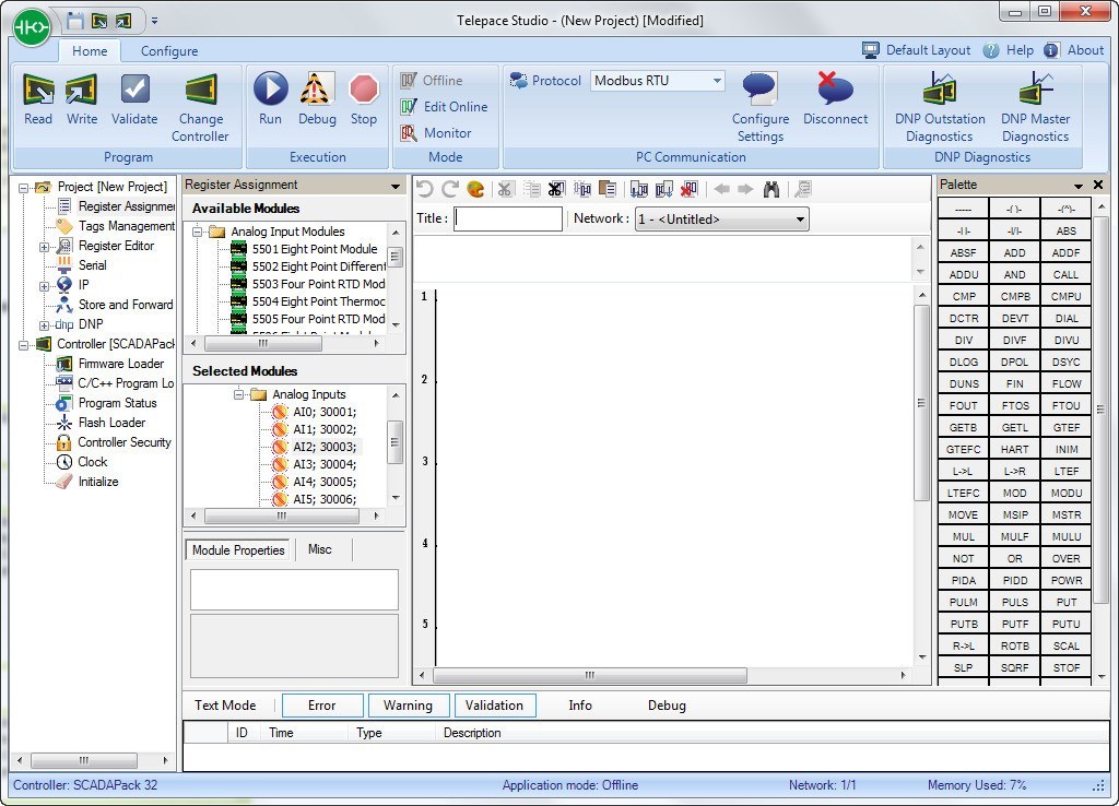

55 STEP 2 MULTIPLY INPUT REGISTER BY 100. 55 STEP 1 SUBTRACT INPUT REGISTER BY 6553 – 4MA = 0. 54 Representing Numbers in the Controller. 51 ADDING HYSTERESIS TO THE PUMP CONTROL. 50 ANALOG INPUT TO START AND STOP THE PUMP. 49 STEP 1 STEP 2 STEP 3 STEP 4 STEP 5 CREATE TAG NAMES. 30 WRITE LADDER LOGIC PROGRAM TO THE CONTROLLER. 26 CREATE AND COMMENT LADDER LOGIC PROGRAM. Then the mouse is used to place contacts, outputs, counters, PID controllers, etc. Using the TelePACE Ladder Editor on a personal computer, tag names are assigned to I/O addresses and data registers. 25 ADD CONFIGURATION AND DIAGNOSTIC I/O MODULES. Relay Ladder Logic programming is simpler than ever with SCADAPack and TeleSAFE line of SCADAcontrollers. 25 CONFIGURE 5000 SERIES I/O MODULES USED IN THE APPLICATION. 24 CONFIGURE CONTROLLER REGISTER ASSIGNMENT.
#Telepace studio full version serial#
24 CONFIGURE CONTROLLER SERIAL PORT SETTINGS. 23 CONFIGURE CONTROLLER FOR SERVICE MODE.
#Telepace studio full version install#
23 INSTALL SERIAL CONNECTION BETWEEN PC AND CONTROLLER.

All other product names are copyright and registered trademarks or trade names of their respective owners.ĬONTROL MICROSYSTEMS SCADA products. Trademarks TeleSAFE, TelePACE, TeleBUS, SmartWIRE, SCADAPack, SCADAWave, and SCADARange are registered trademarks of Control Microsystems Inc. TelePACE Studio Ladder Editor Training Manual ©1999-2009 Control Microsystems Inc.


 0 kommentar(er)
